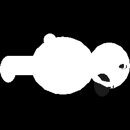

figure 1a: front and back surfaces of a teddy bear(left)
figure 1b: front surfaces only(right)
We present a sculpture generation system that emulates a target
3D model through strategic selection and placement of user-designated
sub-models. The goal of our system is to allow the user to exercise
his/her creativity with the aid of computation. There are three
steps in our sculpture generation pipeline. First, the target
model is converted into a voxelized data structure. Next, with
the information in this data structure, the target model is partitioned
into cubical subparts. Finally, each subpart is replaced by a
strategically chosen sub-model provided by the user. The system
grants the user a high degree of freedom by allowing him/her to
determine how the target model is partitioned, and to define a
collection of sub-models that best convey the theme of his/her
conglomerate sculpture.
Conglomerate Sculpture is a toolkit that allows a user to create interesting and beautiful three dimensional designs. The system does not dictate the exact design, but rather offers possible designs based on both user-specified parameters and choice of source models. By creating this system we accomplish two main goals. One, we enable the computer to make design decisions in order to create an object that is beautiful. Two, we create a system that has infinite variety by offering results composed entirely of the user's own creations.
The dialogue of interaction is simple and powerful. The user first chooses a target 3D model. Then, the user specifies a collection of sub-models, as well as certain constants that affect the decisions made by the system. The system then takes these specifications and produces a design for the conglomerate sculpture. The sub-models are strategically placed in space so as to appear, as a whole, similar in shape to the original target model. The system uses certain computational heuristics to decide the arrangement of the sub-models with the goal of approximating the target.
The aspirations of Conglomerate Sculpture are twofold. One, we wish to explore the possibility of giving a computer an artist's eye. Computational aesthetics is a little explored region of artificial intelligence. Can a computer be taught to make design decisions? Can a computer think about art, and make judgements of beauty? Of course, these are lofty questions, and our project makes no claims to conquering them. What we do attempt is to design a system that uses computational heuristics to create objects of beauty. We took a specific design question and taught the computer how to create a design that is beautiful. Of course, rule-based systems and computation can never approximate the infinite creativity of the human artist. However, our project shows that when presented with a tightly constrained design problem, a computer can make decisions of aesthetics, and conclude that one configuration is more beautiful than another.
The second aspiration is to create a creative dialogue with a
user. It is only marginally interesting to watch a computer struggle
to make artistic creations of its own. It is obvious that what
a computer can create is very limited in scope, and that each
piece of its work will be very similar to the others. Also, this
situation pits the computer artist against the human artist, which
is counter-productive and pointless. Instead, our goal is to create
a tool for the creation of art. Together, the user and the system
can enter a dialogue, and end up with a beautiful result. An added
benefit of coupling computation with human creativity is that
the user need not have specific artistic skills or experience.
We believe that children would especially enjoy this invitation
to explore their own creativity, simply watching a computer crunch
by itself would be much less interesting.
The system will take as input both a target model and a collection of source models that will be used to make up the target model. Then, according to various parameters defined by the user, the system will attempt to build the target model out of strategically chosen, scaled and placed source models. Optionally, the materials of the source models will be changed to match the target model.
The possibilities of the system to exercise the creativity of the user are endless. A peace activist could rebuild a model of an artillery gun out of doves and flowers. Or, an artist could build a human model out of diced up body parts and slimy insects.
The first step is to segment the target model into a collection of cubes. The granularity of the cubes will be a user-defined parameter. If the user wants the target model to be approximated by many small objects, the software will segment the target model into many small cubes. If the user wants coarser granularity, the target model will be approximated by a few, larger cubes.
Next, the system will iterate over the cubes. For each cube, we will choose a model with an orientation that most closely approximates the shape of the portion of the target model that is enclosed in the defining cube.
We hope to animate the entire process. First, the user will see the target model. Then, the user can watch as the model is parsed into cubes. Finally, the user will be able to observe the progress of the algorithm as it fills each cube with a sub-model.This is an optional step that we will take if we have time.
Most of our goals accounted in the previous section have been accomplished. Our system is able to voxelize a target model, partition it into cubical parts according to the user-specified parameters and construct a conglomerate sculpture from user provided sub-models. We did not implement some of the optional features such as matching the material properties of the user model with the target model, animating the voxelization and object replacement process, or exploring some of the more advanced algorithms for parsing models into cubes. In hindsight, these goals were rather unrealistic given our time constraints.
Below is a detailed presentation of the algorithms used in our three main modules: voxelization, cube parsing and object replacement.
The word "voxel" is derived from the words VOlumetric and piXEL. Voxel is a volumetric unit that makes up the discrete three dimentional representation of an object just as pixels in two dimentions. Therefore, to voxelize an object is to decompose it to voxel units of a desired granularity. The voxelization of an arbitrary Inventor model was the biggest challenge we faced during the realization of this project. The design for this procedure has undergone many cycles of evolution. During each cycle, we apply experiences and insights gained from the previous designs to try to come up with a better version.
In the earlier stages of our project, we did not recognize the necessity of voxelization. Our first idea involved dicing up an object into smaller components. This process would slice the target object in half, cap the open faces, and iterate until the diced object filled a certain percentage of the cubical volume that encloses it. In order to implement this algorithm, we will need to be able to cap an arbitrarily shaped cross section and calculate the volume of an arbitrary object. Which turned out to be challenging problems.
This is the point that we recognized the necessity of voxelization. It solves the two problems in our first design. First, we can readily extract volumetric information from a voxelized model. Secondly, since we will be passing around the voxelized representations, object clipping and cross section capping becomes unnecessary. The second design voxelizes by first putting a 3D grid over the model, and for each cube of the grid, do an in-or-out test(cast a ray, if it intersects the object surface an even number of times, the cube is outside of the object; an odd number of times, it is in). The surface of the object is presumably made up of a large number of polygons. This idea calls for a fast polygon intersection determination algorithm.
The third design is based on ray casting as well, but it improves upon the previous one by cutting down the number of in-and-out tests needed. Instead of casting rays from every cube, it casts a ray along a row of cubes from one face of the bounding box to the other, basically performs a 3D scan conversion. We still face the same problem in that we will need a way to prune the number of polygons tested for intersection. Later, after other designs failed. This is the design we came back to and finally got to work.
At this point of the design process, we talked to Prof. Teller. He suggested a hardware approach to achieve voxelization by capping clipped polygons. The high level idea is to define our voxel faces to be the size of a pixel, slice the object into pixel-thin slices, and register a voxel for every pixel shown at the cross section. The union of all the voxels forms the voxelized version of the model. The polygon capping algorithm is used to determine the cross section. The details are as follows:
This algorithm was implemented, but we had trouble getting it to work mostly due to unfamilarity with OpenGL.
While we were stuck, we took the idea from the last design and deviced a way to do cross section capping using Open Inventor exclusively. Instead of rendering the cap to screen, we will save various buffers and calculate the cap manually.
This algorithm has a serious bug in it. We did not discover it until it was fully implemented and we ran it on a test model. The problem arises when the object is not convex, or there are two objects in the same line of sight. The algorithm is based on taking away visible front surfaces from a rendering of both front and back surfaces. This should yield a buffer with visible sections only where a slice intersects the model. However, if there is another section of object behind the one we are slicing, the extra object's front faces show up, and lead us to cut that section out. The following images are of the two buffers resulting from a slice of a teddy bear model. The first image is front and back surfaces, the second is front only. The extra arm behind the body would lead us to carve that section out of the belly.


figure 1a: front and back surfaces of a teddy bear(left)
figure 1b: front surfaces only(right)
The final version is fairly simple, but slow. It is based on the SoRayPickAction provided by OpenInventor, which casts a ray from a pixel in a viewport and returns the polygons hit. So, we took the bounding cube of the object to be voxelized, and then stretched a square viewport across the leftmost YZ face of the bounding cube. The width and height of the viewport are equal to the granularity that we are voxelizing to, generally 128. Then, iterate over each pixel in the viewport and cast a ray in the positive X direction. Inventor then returns a list of the hit polygons. It is possible to determine whether a polygon is an entering or a leaving face by taking the dot product of (1,0,0) with the normal to the polygon face. What results is essentially a simple parenthesization problem. An entering face is an open parentheses, and a leaving face is a close parentheses. I simply turn on voxels where the ray is inside a parenthetical statement, and turn off voxels when the ray leaves. This accounts for submerged shapes (nested parentheses).
The result is a span of voxels, already in a Run Length Encoded format. Our data structure for voxelization uses Run Length Encoding for each span of voxels, since we believe that for normal shapes an RLE span of voxels will have O(1) integers, rather than O(n) voxels. This reduces the size of the data structure from O(n3) to O(n2).
The problem is one of efficiency. It is probable that the Inventor ray picker is a O(f) algorithm, where f is the number of polygons in the model. So, if the granularity of our voxelization is n (generally 128), our voxelization algorithm is O(n2f), which is slow for large, detailed models. So, we designed a file format for voxelization, with suffix .vxl, and ran the voxelization of all of our models overnight. So, the user must perform a pre-processing step on his/her models before using them in the main software.

figure 2: Al.iv -- the target model to be voxelized

figure 3: voxelized version of Al.iv,
the axis shown are the calculated principle axis
The job of the cube parse algorithm is to mimic the shape of a voxelized model by some set of cubes, each of which will later be replaced by a sub-model. Because matching sub-models is a difficult process, we generally seek to minimize the number of cubes used, without sacrificing too much detail inherent in the shape of the original model.
The algorithm starts with an empty list of cubes and a few user defined parameters. A recursive technique is used to partition the model into cubes of varying sizes. First, we imagine a cube enclosing the entire model. Using the voxelized model, we can determine the volume of the model contained in the cube. We also know the volume of the whole cube by simply multiplying its dimensions. A simple division yields the density of the cube, or the extent to which the cube is filled by the model. If the density is greater than some user defined constant, then the cube is added to the list, and the algorithm returns. If the density is less than or equal to some other constant (possibly 0) the cube is not added to the list, and the algorithm returns. However, if the density is between the two parameters, the cube is devided up into 8 subcubes, and the algorithm is called recursively.
In this manner the algorithm progressively considers cubes of half dimension to those that came before. Optionally, the algorithm can also define some limit of recursion. This essentially sets a minimum size for cubes that can be considered for addition to the final list. However, even if no such limit is specified, the recursion will eventually terminate, because the size of the cube considered by the algorithm will over time diminish to the point that it exactly matches a single voxel, which by definition is either on or off. So, it is for aesthetic, rather than computational reasons that a limit can be specified. Below is a sample output of the cube parsed Al.iv image.
figure 4: Al.iv image parsed into cubes.
While this algorithm provides attractive results, it is not as
optimal as perhaps a human would be in selecting cubes to accurately
represent a model. There are several more sophisticated algorithms
that might be used to more optimally partition a vox model. One
of the limitations of the current algorithm is that it can only
create cubes whose edges exist on even log2n voxel boundaries, and whose axes are parallel to those of the
voxel model. A different algorithm might attempt to sweep the
model with progressively smaller cubes in an attempt to match
irregularly in position. When a match was made, the portion of
the voxel model that was matched would be erased, and matching
would continue. In this manner we could slowly represent the whole
model by cubes in a more optimal manner than we do currently.
There are other approaches that could easily be taken. One of
the most obvious is bispace partitioning. We could imagine cutting
up our model along a certain plane, and find the area of the cross
section of the plane intersection. If we iterated this plane through
every position along it's normal, we could find the point at which
the area that the plane slices changes as much as possible. (When
the derivative of area is maximum.) In this manner we could split
the model along it's more natural joints. This also might prove
a more optimal algorithm.
The fitting algorithm accomplishes two main goals. Once a target model has been parsed into cubes, we need to select a sub-model that best fits into each each cube. To accomplish this, a heuristic must be established that evaluates numerically the similarity between two models. Secondly, once a sub-model has been selected, it has to be scaled, translated, and rotated so as to best fit the cube. We have designed an elegant solution to solve both problems by calculating the principle axis of a model.
The principal axis of a three dimensional shape are the axis of maximum rotational inertia, minimum rotational inertia, and an axis perpendicular to these axis. It has been proven in the "Principle Axis Theorem" of geometry that these axis are perpendicular, and that they are centered at the centroid of the model. Thus, they provide a basis in three-dimensional space for the model. If the model is scaled, rotated, or translated, the principal axis follow the shape.
Also, by comparing the moments of inertia about these axis, we obtain a description of the model in the form of three numbers. This is not a complete description, of course, but it does provide a simple heuristic for testing similarity between two models. Once two objects have been scaled so that their bounding spheres are equal, the two objects are similar if their moments about their principle axis are similar.
The difficult step, of course, is to calculate the principle axis and the rotational moments about these axis. In order to calculate this, we first calculate the inertial matrix:

The above triple integrals are calculated over the entire model. Since our models are represented as voxels, these integrals are easy to calculate. Once the inertial matrix is calculated, the principle axis can be found by taking the eigenvectors of the matrix. Note that since the inertial matrix is real and symetric, we are guaranteed 3 independent and orthonormal eigenvectors that form a basis in 3D space. We are also guaranteed 3 real eigenvalues. The largest eigenvalue is the moment of inertia about the axis of maximum inertia, and the other two eigenvalues are the moments about their respective axis. So, once the eigenvalues and eigenvectors are calculated, we have all that we need to fit objects.
Calculating the eigenvalues of a 3 X 3 matrix in closed form involves the solution of a cubic polynomial. This is too difficult, so instead we use an iterative solution to the eigenvalue problem taken from Numerical Recipes in C. The Jacobi Transformation of a symetric matrix is an iterative solution to the eigensystem problem which is efficient for small matrices. So, we used this algorithm to calculate the eigenvalues and eigenvectors of the inertial matrix. The results of the algorithm are unsorted, so we use a simple insertion sort to sort the three eigenvalues and their corresponding eigenvectors.
The last step is to use this data to choose a sub-model and create an Inventor scene graph. The input of the algorithm is the section of the target model that we are matching with a sub-model. This target section must be voxelized and situated in world coordinates. To choose a model, we simply iterate over the sub-models, scale them so that their bounding sphere matches that of the target, and get its eigen system. Note that we do not need to recalculate the eigen system because of scaling. If a model is scaled by a factor k, the eigenvectors are unchanged, and the eigenvalues are scaled by k5. We choose the sub-model that minimizes the sum of the squares of the differences in corresponding eigenvalues.
Once a model is chosen, we need to create a scene graph for the sub-model. First, we translate the model to its centroid. Then, we rotate it so as to align the principal axis. To accomplish this, we need to calculate a rotation matrix. Let us call the 3 X 3 matrix of eigenvectors of the target shape T, and the matrix of the sub-model S. Since these matrices are orthonormal bases in 3D space, one can consider the rotation of the sub-model to be the Identity matrix in the basis of S, and the rotation of the target shape to be Identity in the basis of T. So, we need to calculate a composite change of basis matrix that transforms the Identity matrix from sub-model coordinates to target shape coordinates to world coordinates. This can be done with the following change of basis.
rotation = T-1 * S
So, we calculate this rotation, and rotate the sub-model about it's centroid accordingly. Finally, we translate the sub-model so as to align it's centroid with the centroid of the target shape. The algorithm is done.
Unfortunately, it was not possible to get all the bugs out of the system by the deadline. The system builds conglomerate sculpture fine, but is not able to choose well between sub-models. The problem is that the code does not handle scaling correctly, which does not affect the principal axis but does affect the moments. Therefore, at the moment it is only possible to build conglomerate sculpture out of one sub-model. If several models are passed into the system, it just uses the one whose original bounding box was largest. We hope to fix this bug sometime in the near future.
I helped in the implementation of the voxelization procedure. Although the form of help came mostly in the form of eliminating designs that didn't work. I did alot of research on voxelization, implemented the solid capping algorithm and the Inventor diff buffer algorithm. The first one didn't work due to lack of experience in working with OpenGL's stencil buffer functions. The second one had a serious bug in it as shown in the Teddy Bear pictures. Aseem was the one that implemented the final and working version.
I coded our main.cpp and took on more responsibility in the writing and editing of the report. I also converted and constructed images for this report.
The original idea for the project was mine. I designed the overall structure of the process to create conglomerate sculpures.
I wrote the VoxObject module. This module can voxelize an arbitrary Inventor model, and calculates and returns critical data about the model. This includes the object centroid, volume, inertial matrix, principle axis, and moments of inertia. The module keeps voxelization data, but maintains state that allows it to convert this data into world coordinates.
I also wrote the Fitter module. This module uses the methods of VoxObject to choose a sub-model, rotate and scale it, and create an Inventor scenegraph with this data and a translation to align the centroids.
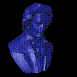
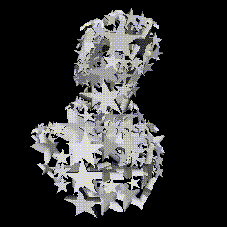
figure 5: Beethovan bust constructed out of stars
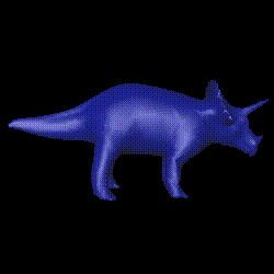

figure 6: triceratops constructed out of stars
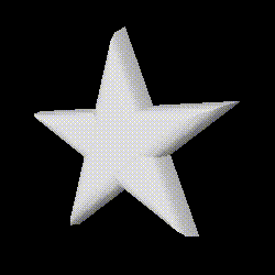
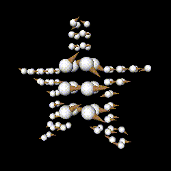
figure 7: star shape constructed from ice creams
The most important lesson we learned through this project is "Be prepared to throw the first design away"(from The Mythical Man Month). It was more like the first 4 or 5 in our case. The key point is that we were able to absorb insights and experiences gained from each cycle of the design process into the realization of our final design.
Prof. Seth Teller for suggesting the capping algorithm using stencil buffer.
Brad Grantham of SGI for giving help with the debugging of the stenciling algorithm.
Luke Weisman for his guidance
Professor B.K. Horn for information on the Principle Axis Theoreom and how to solve for the principle axis. Also, thanks to Professor Horn for discouraging me from try ing to calculate and use Extended Gaussian Images to match shapes.
Numerical Recipes in C for providing the code for a Jacobi Transformation of a matrix.
http://avalon1.viewpoint.com/
for some of our graphics models.
David Difranco, for his ice cream model.
Josie Wernecke, The Inventor Mentor Reading Massachusetts: Addison-Wesley Publishing Company, 1994. Gilbert Strang, Introduction to Linear Algebra. Massachusetts: Wellesley-Cambridge Press, 1993
S. A. Teukolsky, and W. T. Vetterling, Numerical Recipes in C: The Art of Scientific Computing. Cambridge, UK: Cambridge University Press, 1988
Jackie Neider, Tom David and Mason Woo, OpenGL Programming Guide. Reading Massachusetts: Addison-Wesley Publishing Company, 1993.
vxl --> Takes as input an Inventor file and an integer. Creates a voxelization of the Inventor file to the level of detail specified by the integer. Dumps the voxelization to file.
Usage: vxl <file> <granularity>
cparse --> Takes a voxelized file, two floats, and one int. Parses the
input file into cubes, and creates an Inventor representation
of the cubes. Useful for deciding good settings for parsing an
object. TargetDensity is a value from 0 to 1, and tells the algorithm
the minimum filled volume such that a cube is considered acceptable.
MinDensity tells the algorithm to throw away cubes that are less
filled than this number. CubeGranularity puts a limit on how small
cubes can get.
Usage: cparse <inModel> <targetDensity> <minDensity> <cubeGranularity>
cong --> Creates a conglomerate sculpture. Takes a target voxelized
model, a list of voxelized sub-models, and constants similar to
the constants in cparse. Outputs a sculpture.
Usage: cong <targetModel> <list of subModels> <targetDensity> <minDensity> <cubeGranularity>